Sunday, 18 April 2010

Completion of Circuitry


The old circuitry which was built by james worked, however, when trying to make the command system work with the circuitry, we found it hard. This was due to the fact that the circuitry had 3 LDR's and 3 LED's , and our command system was suited to 2 LDRS and 2 LED's . I could have modified the system, however i was more comfortable modifying the circuitry . Below is a picture of the circuitry which was made by James.

Old circuitry


Rebuilding Of Circuitry Using Lecture Notes .


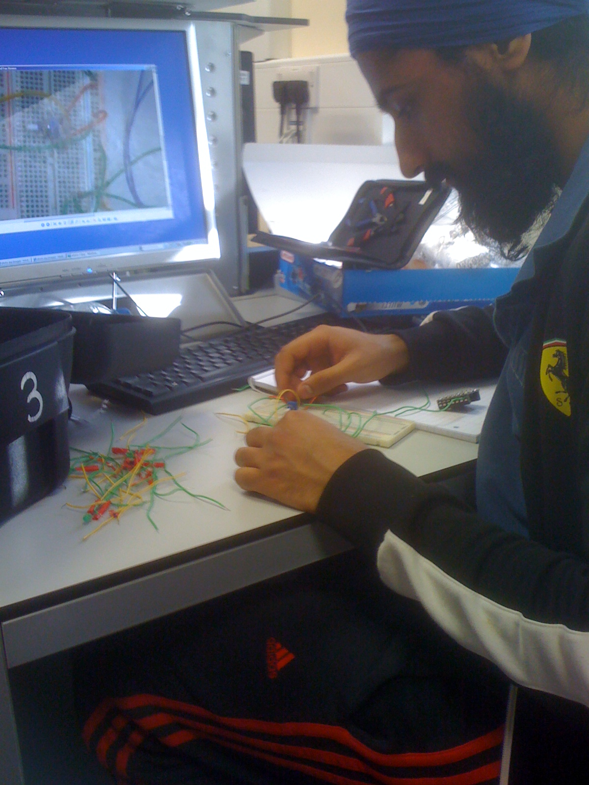
I used the lecture notes to rebuild the circuitry as i found the lecture notes to give clear, easy step by step notes on how to power up the motors easily. I did this for one motor and then connected up the second motor by emulating the first one. The LDR's were connected up after the circuit was complete. I only used 2 LDR's this time and 2 LED's in the circuit.


New Circuitry ( Simple and a lot less complicated )


Pictures of the final circuitry will be given in later posts as we still may need to modify it slightly, example extending the LDR's under the chassis , however, the circuitry shown above was taken a picture of as i was coming near completion.

Saturday, 17 April 2010

Meeting 3 ( 17/04 /2010)

Important aspects discussed in our meeting were :

  • The chassis has been made and the circuitry is complete .
  • The program nearly works with the circuitry but for some reason the chassis is not functioning the way we would want it to . There seems to be some sort of problem , hence over the next week we need to work together to see what the problem is and to make the chassis work .

Friday, 16 April 2010

Advanced Command system

The previous commands were working however, there was too much of a wait in between some stops. Hence i have modified the system to suite the circuit a bit better.

main:
readadc 1, b1
readadc 2, b2

select case b1

case 60 to 255
low 2
high 1
case 0 to 59
high 2
pause 600
low 1
end select

select case b2

case 60 to 255
low 4
pause 200
high 3
case 0 to 59
high 4
low 3
end select

debug b1
debug b2
goto main

Command Development

Although the previous command was tested, it did not work. Therefore it is important that we have a command which actually works. The command below has been tested and is a lot more realistic for the buggy design in accordance to our circuit. It consists of case statements and is not too long !

main:
readadc 1, b1
readadc 2, b2

select case b1

case 60 to 255

low 2
high 1
case 0 to 59
high 2
wait 3
low 1
end select

select case b2

case 60 to 255
low 4
wait 3
high 3

case 0 to 59

high 4
low 3
end select

debug b1
debug b2
goto main

As you can see, there are onloy 2 case statements. One for one LDR and the other is for the second one. The circuitry has 3 LDR , therefore, the circuitry either needs to be modified , or the command need to be modified .

Thursday, 15 April 2010

Full view of circuitry

This is a photo showing the full circuitry, including the motor and the control boards, before the changes were made to give our final circuit.

Photos of the circuit


Here are some photos of various parts of the circuit.


This is the control board with the various inputs and outputs connected.

We used different colours to try to make the circuit easier to create.


This is a photo showing the LDR's on the top, with some LED's wich we decided to remove, and possibly add in later, if we needed them:

We altered the resistors to 100K ohms to help ensure the circuit worked as we wanted it to.

Circuit Diagram


This is an older circuit, which we altered, to try and make more simple.
We decided to try to alter the circuit so we only had two LDR's, for simplicity in the programming, and so that there would be less that could go wrong.
The switch connected to pin 7 is the selector switch.
The LDR's had to be connected to pins 0,1,2 because they are the analogue pins, which were needed to read the signal from the LDR's. Pin 7 is a digital input. As shown, the motor board is the same as the other diagram, just drawn differently.