Before saying anything about the project, I would like to say thank you to all my groupmates. At least, they did not kick me out of the group even I am stucked abroad for the most essential week.
On the project
We spilted this project into three area at the beginning. Programming, circuit and the physical components (wheels, gears, chassis). I was mainly involved in the program and the chassis bit.
Programming
Before Easter, Park and me started to draft the program. We break it down into parts. Basically, 4 functions are required. Power on/off, turn left/right, walk in stright line and reverse. We did some simulation in PICAXE but unfortunately I did not save it since that was the very first draft and that is it really before Easter.
Chassis
We disscused on this for kind of long because we have been changing our idea quite often before. Originally, I was about to bring a box-shaped chassis back. Well, the volcano in Iceland erupted. So, my fellow groupmate decided to get something better, meccano.
After all, it is such a shame that I could not take part in the assembling part, and again, I would like to thanks my groupmates. Althought it did not make it through the test, I can see we all learnt something from this project.
Thursday, 29 April 2010
Wednesday, 28 April 2010
possible project improvements: personal opinion
If i were able to do this project again, i would change the following things;
- Power supply - As a group we found that at 4.5v, the buggy was vastly underpowered even with a light chassis.
- 2-pole DC motors - The motors supplied, basically lead to the demise of our project. we were under the assumption that all the contents of the toolkit were functioning 100% correctly, this was not the case. Some groups were having problems with the motors circuit, but both our motors had bad connections.
- Wheels - one of our wheels had a very large hole, meaning the axel and hole fit was too loose. this lead to the axel rotating, but the wheel remaining stationary.
- Planning - as a group we should have left more time for the atual testing of buggy, once constructed.
- Prioritising - the four main parts of this project were the chassis, program, circuitry, testing. we focused on the programming side for far too long, meaning the tasks were left till later.
Project demonstration: reflection
This tuesday just gone our buggy was put through its 'test' aka demonstraion. photos and videos from the day will be upload soon including it actually working!
Over the holiday period, due to the icelandic ash caused by the volcano, our final chassis was stuck with our chassis designer in Hong Kong! This meant we had to create a new chassis before our circuit and program could be tested. Before and during the holiday period, as a group we were focussed on the programming and left the chassis till the end which in hindsight was definetly a bad idea (although who knew about the volcano problem prior to it errupting?).
TEST DAY
We had just completed everything by monday night, and we only needed to fine tune the chassis which we would have done on the day. 2 hours before the demonstration, our buggy had completly stoped working. this was due to one motor failing. During the duration of the project, we constantly had problems with the two motors which were supplied. We first thought there was a problem with our circuit, then we thought it could be the program and finally the sensors. The batteries were also replaced but with no luck.
After ruling all these out in the fault diagnosing process, we found that the cables connected to the reverse of the motors were to blame. It was due to a bad connection as if they were moved about, the cogs in the motor would 'flicker' into life.
 As no replacement motors were available, we had to solder the wires to improve the connection. Fixing the actual problem was relatively fast once a soldering iron was sourced. The actual fault diagnosing was very time consuming. Once both motors were soldiered and the wires replaced, we encountered a short circuit. I am not sure how this could have happened but even the lecturer confirmed our suspicion.
Tuesday, 27 April 2010
Testing Of The buggy
Today we tested the buggy and it was not functioning at the time when we needed it to. It was functioning fine this morning, however, unfortunately i did not understand why the buggy was not even programming when we needed it to. The buggy may have short circuited as we were trying to fix the problematic motor once again.
Problem?
The problem in my view was the connection leading to the motor . We tried to solder it many times and as we pressed on the blue wired connection, the motor would start to run. We tried everything , however, i personally think the batteries were accidentally left connected when trying to solder. This may have short circuited the buggy as we were in a desperate rush to atleast get the buggy moving again just before the test.
What would be done differently if i was to do this project again ..
I would stick to simple circuitry like the one which we had to rebuilt to. I would leave a lot more time to test the buggy for following the line and would want do the connections for the wires as strong as possible the first time around.
What was suprising about the project ?
One definate thing i found suprising was how many times the buggy defunctions . This is what i would take into consideration in future project. Everyday there was something which was failing, if not one thing, it was another. It has been a true practical learning experience that theory in reality does not always compute.
Technical Problems / Improvements
Two LDR's were placed on either side of the black line. In our design, especially from the pictures of our design, if both read light, the buggy would go forward ( which can be seen from the programming aswell. If one read darkness, the buggy would turn. We got to test this out , however, the testing was cut short as we had a motor problem near the time of testing. However, When the LDR's were covered ( with paper) which can be seen from our buggy pictures posted earlier, the buggy did follow the line better. The LDR'S were paried with LED's . This was due to the fact that as the LED went over the black line, less light would be reflected to the LDR. Each LDR was paired with an LED and covered in black paper so that it had a control light setting. As the LED moved over the black line it would reflect less light into the LDR. An improvement to the system would be to have a third LDR as we originally planned which would always be exposed to darkness. This would have been the middle LDR and would have made sure out buggy would not have strayed off the line. In addition, more could have been done with the paper cover of the LDR's to stop light comming in. This could have been made more stylish and more effective, however, we found this was not possible due to our own lack of time management.
Friday, 23 April 2010
Funtioning Of The Chassis.
There were quite a few ups and downs in this project. The wheels were rotating and we could set the LDR's to follow the line. However, there seemed to be a fault with the right motor and we had to halt the testing of our buggy whilst following the line. We had to focus on the right motor. In this process, we did quite a few things to test the right motor. One of the things we did was to change the wires of the left motor with that of the right. The video of us doing this is shown below.
Changing of Wires
Changing of Wires
There was no result in the functioning of the right motor.
We also connected the wires to the actual motor to see if the motor was not damaged. The wheel at this point did rotate meaning it was something in the circuitry ( which we doubted ), or the connection of the wires was not strong via the soldering.
When we re soldered the wires to the right motor , it started to work. This stage can be seen in the video below.
Finally Working Again
We then connected the circuitry back up to the chassis to see if the power of the right motor was enough to drive the chassis forward again. The video of this can be seen below.
Moving Again
We can now finally configure the chassis to the right setting of the LDR's to make the buggy follow the line !
Hopefully you can all meet me tommorow so we can get this done.
Tuesday, 20 April 2010
Building & Development Of The Chassis
I thought it would be an easy task to build the chassis, however it was not as easy as seemed. This was due to the fact that the screws and bolts were very small and fidly. The progression when making the chassis was all recorded by taking pictures of the chassis at different stages. These can be seen below.

I first started off by building the main body of the chassis which can be seen from the picture above. It seemed to be the strongest way of building the base.

The progression of the chassis can be seen from above as i added a diagonal strip and attached it to the main body to give the circuitry some protection from falling out and this also made the body of the chassis stronger. The strip you can see at the front is for the rotation of the front wheel .


The two pictures above, show the completed body of the chassis without any of the circuitry and wheels. For extra presentability, a chair was added to the chassis above the block situated at the back of the chassis. The design proved to be strong when holding the circuitry and batteries. This can be seen in the picture below.

The picture above is the chassis holding the circuitry . A better effort could have been made for tidying up the wires on the chassis , however, greater this was not done as we had issues with making the chassis turn when following the line.

A clearer view of the wheels and the LDR's is presented in the picture above. We had to put a cover over the LDR's for their proper functioning and the chassis was following the line. However, unfortunately, one day before the date of testing, our right motor stopped working for some reason, which in my view was unfortunate as the buggy was functioning one day before the test. Also, the backwards slop of the buggy allowed the batter to sit under the circuitry and not move out of place. This can be seen in the picture above.
Monday, 19 April 2010
Completed Programming
main:
readadc 1, b1
readadc 2, b2
select case b1
case 78 to 255 ; LDR doesn't detect light
low 1
high 2
case 0 to 77 ; LDR detects light
high 1
low 2
end select
select case b2
case 60 to 255 ; LDR does not detect any light
low 3
high 4
case 0 to 59 ; LDR does detect light
high 3
low 4
end select
debug b1
debug b2
goto main
Sunday, 18 April 2010
Completion of Circuitry
The old circuitry which was built by james worked, however, when trying to make the command system work with the circuitry, we found it hard. This was due to the fact that the circuitry had 3 LDR's and 3 LED's , and our command system was suited to 2 LDRS and 2 LED's . I could have modified the system, however i was more comfortable modifying the circuitry . Below is a picture of the circuitry which was made by James.
Old circuitry

Rebuilding Of Circuitry Using Lecture Notes .
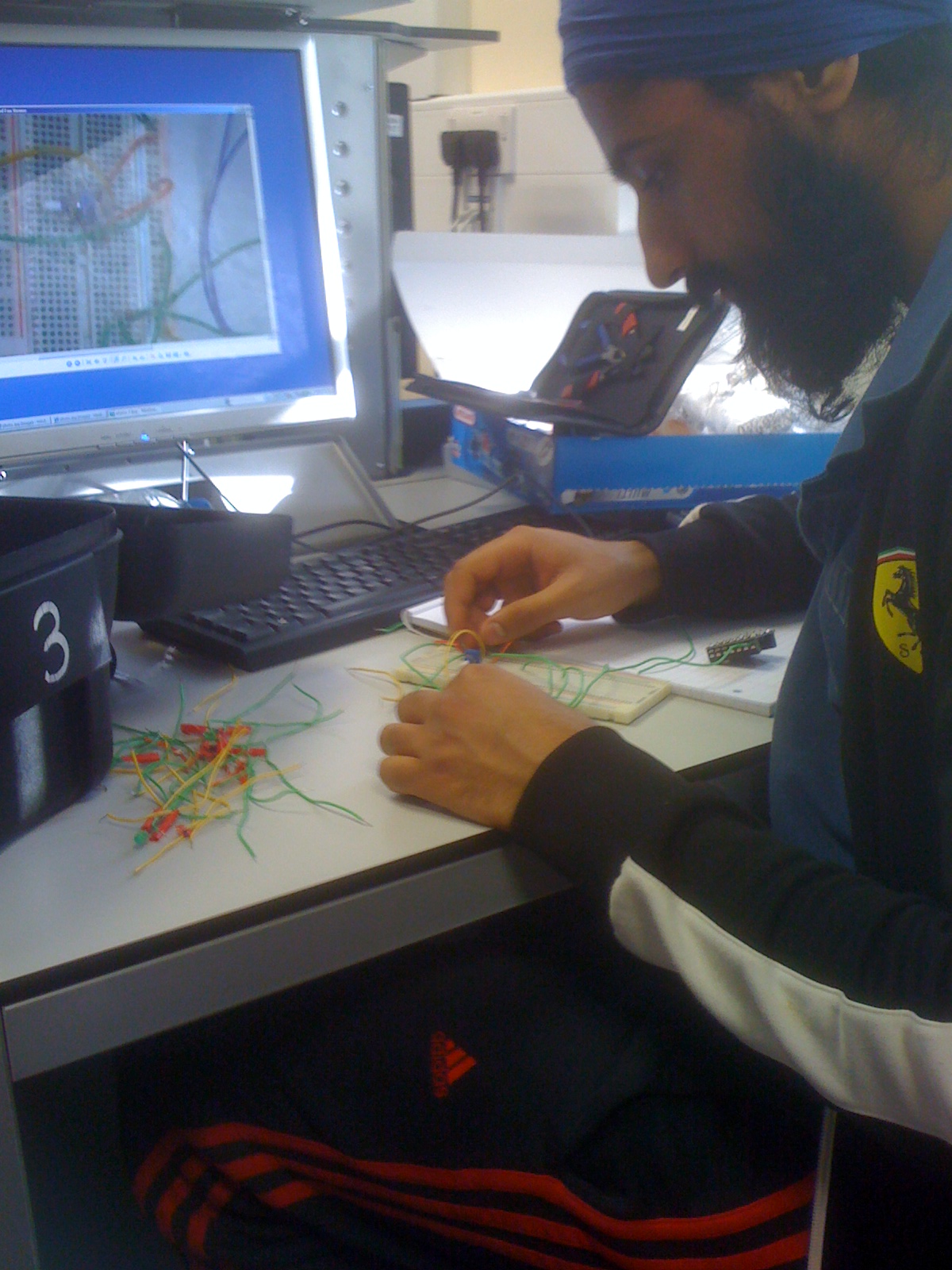
I used the lecture notes to rebuild the circuitry as i found the lecture notes to give clear, easy step by step notes on how to power up the motors easily. I did this for one motor and then connected up the second motor by emulating the first one. The LDR's were connected up after the circuit was complete. I only used 2 LDR's this time and 2 LED's in the circuit.
New Circuitry ( Simple and a lot less complicated )

Pictures of the final circuitry will be given in later posts as we still may need to modify it slightly, example extending the LDR's under the chassis , however, the circuitry shown above was taken a picture of as i was coming near completion.
Saturday, 17 April 2010
Meeting 3 ( 17/04 /2010)
Important aspects discussed in our meeting were :
- The chassis has been made and the circuitry is complete .
- The program nearly works with the circuitry but for some reason the chassis is not functioning the way we would want it to . There seems to be some sort of problem , hence over the next week we need to work together to see what the problem is and to make the chassis work .
Friday, 16 April 2010
Advanced Command system
The previous commands were working however, there was too much of a wait in between some stops. Hence i have modified the system to suite the circuit a bit better.
main:
readadc 1, b1
readadc 2, b2
select case b1
case 60 to 255
low 2
high 1
case 0 to 59
high 2
pause 600
low 1
end select
select case b2
case 60 to 255
low 4
pause 200
high 3
case 0 to 59
high 4
low 3
end select
debug b1
debug b2
goto main
main:
readadc 1, b1
readadc 2, b2
select case b1
case 60 to 255
low 2
high 1
case 0 to 59
high 2
pause 600
low 1
end select
select case b2
case 60 to 255
low 4
pause 200
high 3
case 0 to 59
high 4
low 3
end select
debug b1
debug b2
goto main
Command Development
Although the previous command was tested, it did not work. Therefore it is important that we have a command which actually works. The command below has been tested and is a lot more realistic for the buggy design in accordance to our circuit. It consists of case statements and is not too long !
main:
readadc 1, b1
readadc 2, b2
select case b1
case 60 to 255
low 2
high 1
case 0 to 59
high 2
wait 3
low 1
end select
select case b2
case 60 to 255
low 4
wait 3
high 3
case 0 to 59
high 4
low 3
end select
debug b1
debug b2
goto main
As you can see, there are onloy 2 case statements. One for one LDR and the other is for the second one. The circuitry has 3 LDR , therefore, the circuitry either needs to be modified , or the command need to be modified .
Thursday, 15 April 2010
Full view of circuitry
This is a photo showing the full circuitry, including the motor and the control boards, before the changes were made to give our final circuit.

Photos of the circuit

Here are some photos of various parts of the circuit.
This is the control board with the various inputs and outputs connected.
We used different colours to try to make the circuit easier to create.
This is a photo showing the LDR's on the top, with some LED's wich we decided to remove, and possibly add in later, if we needed them:

We altered the resistors to 100K ohms to help ensure the circuit worked as we wanted it to.
Circuit Diagram

This is an older circuit, which we altered, to try and make more simple.
We decided to try to alter the circuit so we only had two LDR's, for simplicity in the programming, and so that there would be less that could go wrong.
The switch connected to pin 7 is the selector switch.
The LDR's had to be connected to pins 0,1,2 because they are the analogue pins, which were needed to read the signal from the LDR's. Pin 7 is a digital input. As shown, the motor board is the same as the other diagram, just drawn differently.
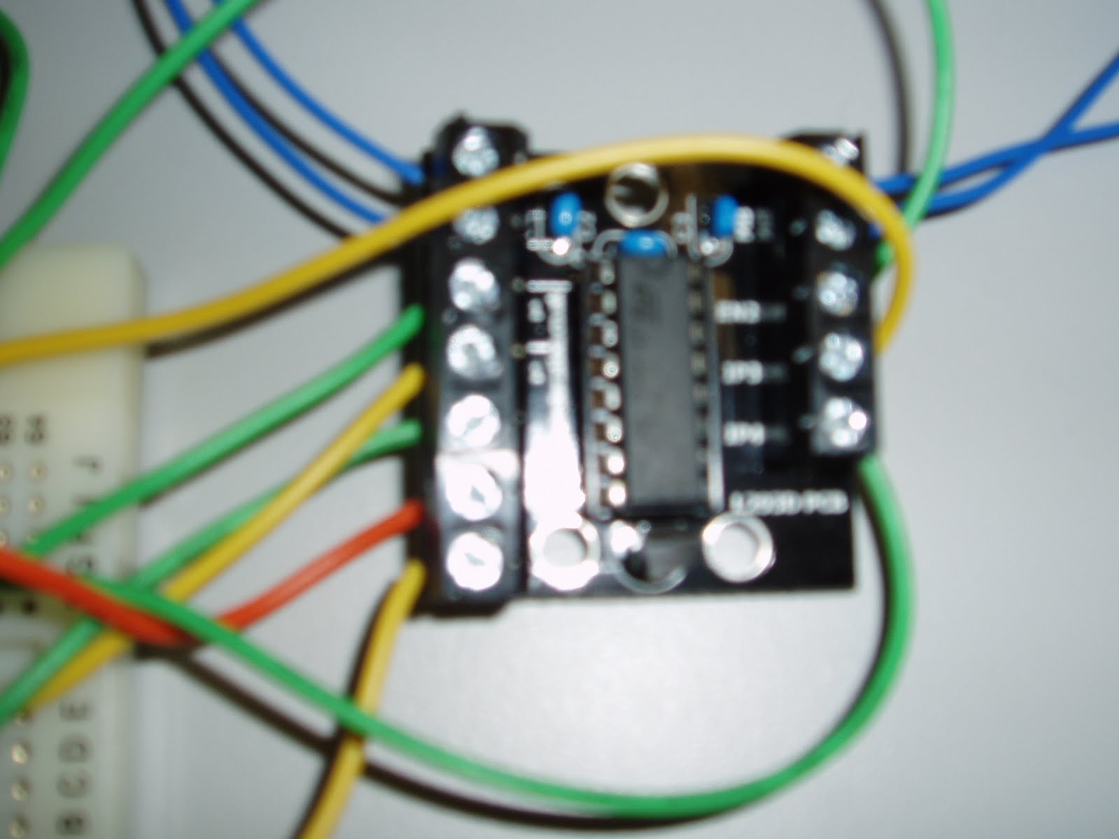
Photos of the motor board
Here are two photos showing the motor board, as shown in the circuit diagram.
The top two blue lines on each sides are connected to the motors.
The bottom red and yellow on the left are the positive and ground rails respectively.
The green lines below the motor lines are the enable lines, 3rd down on each side.
The two remaining on each sides are from the output of the chip which control the motors direction

Wednesday, 14 April 2010
Body Of the chassis

Although the chassis made out of a container would be ok, i thought it would be a better idea to make the chassis out of something a bit more sophisticated. ...... meccano!
Here is the exact set i am getting to build the chassis ! I will make it just right for the circuitry and we should be making the chassis work very soon !
Wednesday, 7 April 2010
Resistor reference chart

This is the resistor reference chart i drew up, to easily tell the value of a resistor.
For example, a typical resistor of:
Red Red Brown Silver
would have a value of:
220 ohms with a tolerance of 10% about that value
Tuesday, 6 April 2010
Initial command
symbol switchstate = input7
main:
switchstate = pin1
debug switchstate
goto work1
if input7 is on then work1
end
work1:
if input1 is on and input2 is on and input6 is on then go_f
if input2 is on and input1 is on then go_l
if input6 is on and input1 is on then go_r
goto go_s
go_f: let pins = %10100000
goto main
go_l: let pins = 100000
goto main
go_r: let pins = %10000000
goto main
go_s: let pins = %01000000
goto main
Subscribe to:
Comments (Atom)